

Mihai MIRON
The magic about the art of paper folding is that from the same sheet of paper one can create so many different objects. Unfortunately, the functionality of such paper artifacts resides only in the human imagination. The possibility to manufacture real functional objects following the principle of Origami would make engineering a child’s play.
In this spirit, we propose a technologically relevant concept addressing magnetic data storage: the lithographically defined shape of the magnetic object determines its magnetization reversal. Objects with identical composition and subjected to the same electric current undergo different magnetization reversal, due to their different geometry.
The angular momentum required for magnetization reversal is provided by the current induced spin orbit torques. The role of the device geometry is to set the spatial distribution of torque inside the ferromagnet.
In practice, we use Kerr microscopy to examine current driven domain wall motion in Co/AlOx wires with different shapes and orientations on top of a current-carrying Pt layer. The displacement of the domain walls is found to be asymmetric with respect to the angle with the current and nonlinear with respect to the current polarity. Using these insights, we build, from the same perpendicularly magnetized thin film, bipolar switches typically used for memory devices as well as irreversible switches where shape controls the magnetic orientation regardless of the current polarity (Figure1).
Since this method is generic for angular momentum transfer by in-plane current, it can be used with a wide variety of materials, ranging from simple heavy-metals to topological insulators. Last but not least, the concept of geometric switching enables the design of magnetic devices whose functionality is fully determined by the choice of their lithographic shape, the simplest and most flexible step in the fabrication process.
http://www.nature.com/nnano/journal/vaop/ncurrent/full/nnano.2015.252.html
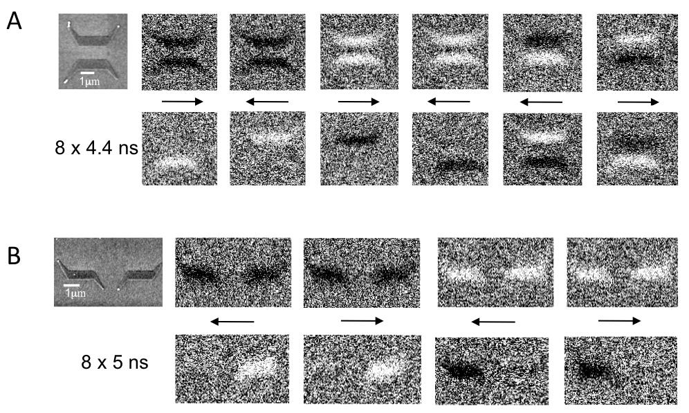
Figure: Geometric magnetization reversal. (A) Bipolar switching of “u” shaped devices. The first row contains an SEM image of the magnetic structure sitting on top of the much wider rectangular Pt electrode (not visible). The subsequent differential Kerr images correspond to the initial magnetic state of the devices (bright-down; dark-up). The second row of images corresponds to the final magnetic configuration of the devices after the injection of 8 pulses (4.4ns at j = 1.87·1012 A/m2). The electric current is indicated by black arrows. The comparison of the initial and final images, confirms that the two objects behave as bipolar switches with reversed polarity (B) Switching of “s” shaped devices. The first row contains an SEM image of the magnetic structure, followed by the differential Kerr images of the initial state. The images on the second row illustrate the final state produced by the injection of 8 current pulses (5ns at j = 1.87·1012 A/m2). While one of the objects only switches up, independently of the current, the other object only switches down.